Finishing Morph Operation – SprutCAM America

How to Machine Holes with CAM
March 5, 2019
Creating a Tool Table – CAM Software
March 5, 2019One of the most useful operations is also the most underused. The finishing morph operation generates toolpaths between two curves, using sync lines to improve the toolpath. You have the option to have them run along, across, or spiral between the curves. This tool path can be used with everything from 2-axis to 5-axis, with the tool axis orientation allowing you to choose between fixed, normal to curves, normal to surfaces, or normal to rotary axis. The demo below shows how to do a spiral toolpath down the machining surface of a cone shaped model. There are many other uses for morph, so try it out and play around with it!
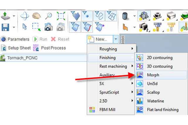
1. Create a New Finishing Morph Operation.

2. Go to Job Assignment in the machining tab and choose the machining surface.

3. Select the First Curve and Second Curve. These are two edges that are parallel to each other in any plane.


4. Select any sync lines that better define the surface and model.

5. Set the Strategy parameters. Choose Spiral and set the Step (depth of cut). Tool containment can also have an effect on the result so play with that.

6. Run the operation after setting the tool (I’m using a 1/8 Ball Endmill).


